Maker tool
Turn your living room into an escape room.
With the maker tool you can connect to a wealth of electronic parts. But that's just the beginning. With the power of the central controller behind you, you could make different creations all react to each other.
Making making easy.
Just add creativity
Make your own smart devices.
Connect to a wealth of sensors and actuators.
Binary and analog input
Connect switches, potentiometers, motion sensors, gas sensors.. etc!
Binary and servo output
Make it move. Connect up to two servos and two relays.
Make rules and automations
Make your devices respond to the situation in your smart home.
Build it
Connect any combination of sensors and actuators you need.
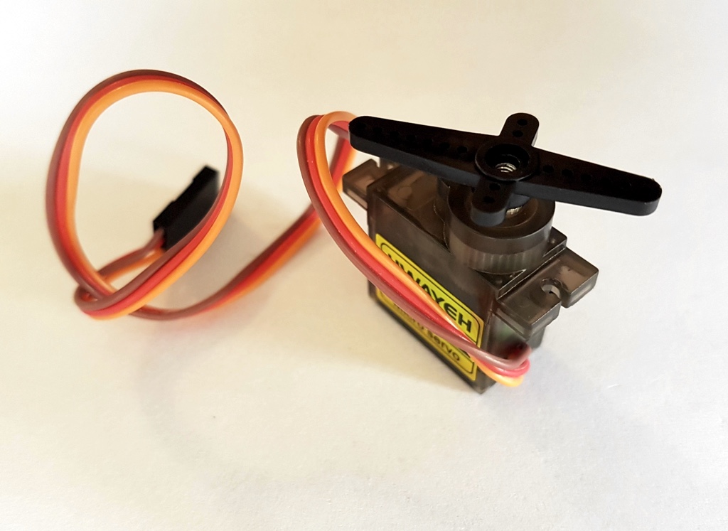
Pulse Width Modulation: servos
Connect the red wire (positive) to any available VCC pin on the expansion board. Connect the brown wire (negative) to any available GND pin on the expansion board.
Only small servo's (such as the one pictured) can be powered from the Arduino directly.
Binary input: switches and on-off sensors.
Connect you device's VCC (positive) to any available VCC pin on the expansion board. Connect the GND (negative) to any available GND pin on the expansion board.
Connect the sensor's signal/data pin to signal pin 2 on the expansion board..
An second sensor can be connected, this time using pin 3 instead.
Binary actuator - LED's or relays
Connect you device's VCC (positive) to any available VCC pin on the expansion board. Connect the GND (negative) to any available GND pin on the expansion board.
Connect your actuator's signal/data/in pin to the signal pin 4 on the expansion board.
You can connect an additional actuator, this time using pin 5 instead.
Analog input: potentiometers and various sensors
Connect you device's VCC (positive) to any available VCC pin on the expansion board. Connect the GND (negative) to any available GND pin on the expansion board.
Connect your device's signal/data pin to the A0 signal pin on the expansion board.
You can connect an additional analog sensor, this time using pin A1 instead.
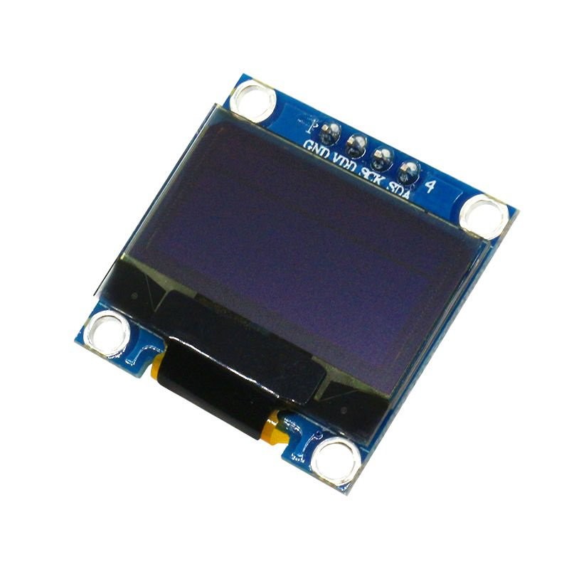
Text display
Connect the screen's SDA (data) pin to signal pin A4 on the expansion board. Connect the screen's SCK (clock) pin to signal pin A5 on the expansion board.
Connect the screen's VCC (positive) pin to any available VCC pin on the expansion board. Connect the screen's GND (negative) pin to any available GND pin on the expansion board.
Examples
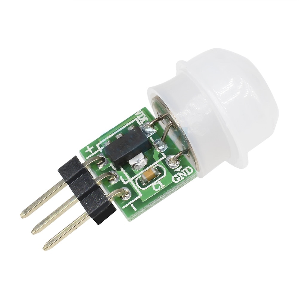
Pin 2 - Binary sensor A
Pin 2 and 3 can be used to connect binary sensors. In this example you see a PIR motion sensor.
Pin 3 - Binary sensor B
Pin 2 and 3 can be used to connect binary sensors. In this example you see a simple button. There are also nice ready-to-go switch boards.
Pin 4 - Binary actuator A
Pin 4 and 5 allow you to switch something on or off. Here you see a basic LED. There are also nice ready-to-go LED boards.
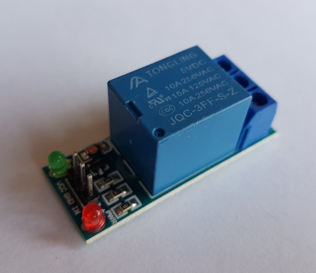
Pin 5 - Binary actuator B
Pin 4 and 5 allow you to switch something on or off. Here you see a relay.
Pin 6 - Servo A
Pin 6 and 7 allow you to connect a servo. Servos are a lot of fun. If you have two you could already build a little robot arm.
Pin 7 - Servo B
Pin 6 and 7 allow you to connect a servo. Servos are a lot of fun. If you have two you could already build a little robot arm.
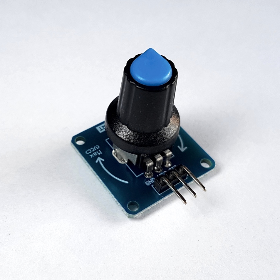
Pin A01 - Analog sensor A
Pin A01 and A02 allow you to connect analog sensors. These sensors can give you a range of values between 0 and 255. Here you see a rotary knob board.
Pin A02 - Analog sensor B
Pin A01 and A02 allow you to connect analog sensors. These sensors can give you a range of values between 0 and 255. Here you see a light intensity sensor.
Pin A04 and A05 - OLED Display
You can output text to this display.
Plug in the RF-Nano Arduino
Plug the RF-Nano into its socket. The USB connector should be on the outside of the main board.
Open the Candle Manager
Select the Candle Manager from the menu, and follow the steps. It will help you upload the code to your new creation.
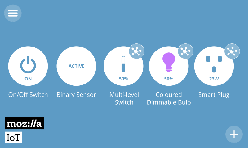
Add your new device
Visit the Candle controller and on the things page press the (+) icon. Your new creation should be available. Optionally, select which of its properties you'd like to have in the spotlight. Click on "save" to complete the proces.